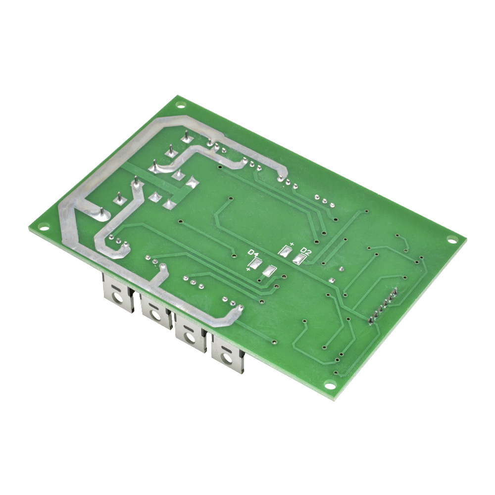
#H bridge mosfet driver board how to#
max voltage? I'm running 24v, so I can tie VCC and VCC2 of my mc33883 chip together (the limit on vcc2 is 28v but I could have separate supply and have a max VCC voltage of 60v) How to power the Arduino? I went with a small 5v 500mA switching regulator which comes prebuilt on a pcb with 3 pins which operates between 6.5-36v perfect!. with parallel FETs this resistor helps to balance the load and switching characteristics of the parallel pair (research more for high loading to avoid issues)ĭecisions to be made. The one difference we will add to the circuit is the optional paralleled MOSFETs to increase current capability to do this we just need to ensure we have a resistor on the gate of each FET. We will use online tool EASYEDA () to design the circuit (not affiliated but the tool works alright and easy ordering of PCB through ) From the datasheet for the MC33883 driver, we can find the application schematic (with external protection circuit) we will copy this circuit as we don't need to reinvent the wheel here just use the recommended layout and recommended capacitor values, we will add the 18v zener diodes and capacitors to cap the gate-source voltage below the typical MOSFET 20v max Vgs With this chip in mind, we can now design our circuit around it Negatives unfortunately does not have shoot through protection (so must be done in software and tested with current limited power supply) requires 5 input signals rather expensive at $8.44 each on mouser.


#H bridge mosfet driver board drivers#
this IC takes HIGH/LOW signals from the Arduino and outputs the same boosted signal to drive the MOSFET gates, specifically its most important function is to increase the voltage to the high side fets above VCC (battery + input) allowing for the use of all N-MOSFETs some drivers also have special circuitry to prevent shoot through (when 2 fets create a direct short circuit to ground destroying the fets.) i eventually settled on the NXP MC33883 Full H-bridge driver IC chosen because - it includes 2 half bridges (so i only require 1 IC) - built-in high side charge-pump - requires only 7 additional components (including protection circuit) - operates with 5.5-60V input (with under and over volt lockout) -1amp peak drive current The H-bridge driver IC is the chip between the Arduino and the MOSFET outputs.


 0 kommentar(er)
